Introducing the 340R Boost Tube
by Peter Crook
The Problem
In order to achieve type approval for construction of
the 340R, Lotus Cars have had to make several compromises relating to drive
by and static noise levels.
These compromises include :
- The fitting of an inlet air butterfly control valve – operated by the engine management system, this valve restricts the inlet air under European type approval drive-by noise conditions, thus allowing the car to comply. The valve has no other beneficial effect and reduces the performance of the car. (the Editor recommends that all owners wishing to improve driveability, disconnect or remove this valve as per instructions found elsewhere on 340r.net)
- The direction of the engine air inlet flexible duct is directed not towards the air inlet pod, but towards the bottom of the engine compartment. Whilst this reduces noise, it also has the undesirable effect of drawing hot air which has been in contact with the exhaust manifold into the engine. Hotter air means less horsepower.
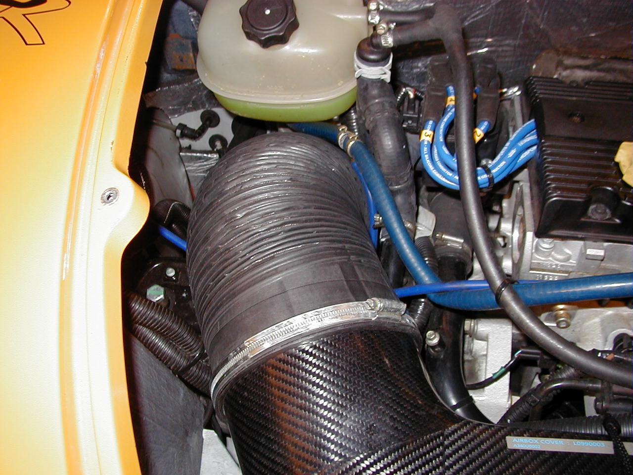
One of the features of the 340R engine over the standard engine is that it has an inlet runner & throttle per cylinder, supplied via a large volume carbon airbox with 6” dia inlet ducting. In a standard elise the inlet ducting connects to the left side air inlet pod which draws air in from the mesh which you can see at the side of the car.
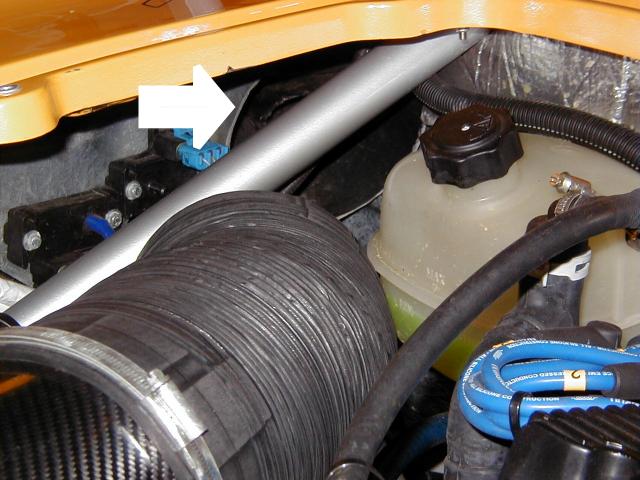
On a 340R the passenger side inlet pod is fitted with a circular spigot, which could in theory, accept fitment of the airbox flexi duct. In practise, the rollbar rear strut is in the way and the duct cannot be fitted to the spigot without squashing. As a result Lotus recommend that on upgraded cars and cars without the air restrictor valve, that the airbox flexi duct be positioned so that it is pointing as closely as possible at the inlet pod spigot (but not connected to it, the theory being that this will draw in colder air than the standard arrangement which takes quite a lot of heat off the exhaust manifold. Whilst this is an improvement over the standard arrangement, the lack of a sealed connection to ambient air means that a mixture of outside air and engine bay air is drawn into the airbox. This is not an ideal arrangement for extracting maximum performance and efficiency from the car.
The Speculation
In early January 2001 a Glen Harman published pictures on the 340R egroup of a two into one connector which split the six inch air duct into two separate smaller ducts which could then be passed around the roll cage and joined into the single spigot on the back of the pod with an adapter.
However after Glenn had removed the air inlet pod for cleaning, he noticed that whilst the spigot was six inches in diameter on the engine compartment side of the pod, the actual free area on the other side of the pod seemed greatly restricted by its construction.
In further discussions with Glenn the comment was made that “perhaps what we need is a formula one style ram air inlet”.
This comment got me wondering if such a thing
might be feasible using a redesigned engine compartment lid.
My initial thoughts were :
-
It must have an equivalent cross sectional area to six inches in diameter.
-
It should be located on the left side of the engine bay away from the heat of the exhaust manifold.
-
It should take air in from as high as possible and from a clean air stream in order to take in the coldest possible air with the maximum ram effect.
-
It should be easily fitted and able to be swapped back to standard configuration.
-
An enlarged free mesh area should be incorporated to improve engine compartment cooling (some high powered Elise’s have suffered from overheating and owners have resorted to drilling additional holes in the rear bulkhead) Air entering the left side pod is also available exclusively for engine compartment cooling.
I contacted Simon Farren of Reverie Limited (an ex Lotus employee) and he agreed that he could design and construct one in carbon fibre to the above brief. An integral part of our agreement was that he would be able to sell the final; design to other interested owners.
Implementation
After discussing the design with ReVerie Limited’s
designer I left my car with them so they could
collect surface data off the car to generate a 3d cad model of the rear
engine cover and roll hoop position. This then allowed ReVerie Limited’s
designer to style and develop a suitable 3d scoop model.
A few days later the
3d cad models showing the shape of the boost tube were finalised and the
full scale patterns were developed.
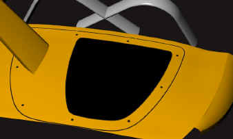
Cad rendering front view of the Boost Tube:
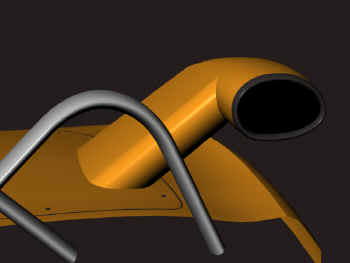
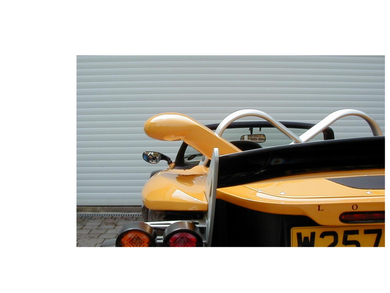
When I saw the model in the flesh for the first time I was very pleased, the egg shaped inlet and aerodynamic downtube looked in keeping with the overall design of the car and the angles harmonised with the crossed members of the roll cage which is a dominant feature of the upper half of the car (it’s almost a shame there’s not room for a matching one on the right hand side – then it really would look like a star wars Ti Fighter!)
The down tube was to be fitted with a six inch circular spigot on the underside of the lid which could be simply connected to the existing flexi duct which was turned upwards and secured with a single large jubilee clip.
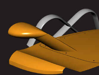
Cad rendering enlarged grille view of the Boost Tube:
The entire assembly was to be constructed from carbon fibre for minimum weight and maximum strength and painted in matching body colour but with a matt carbon fibre inlet cowl nose. The neck was to have an internal turning vane to smooth the airflow.
The Finished Article
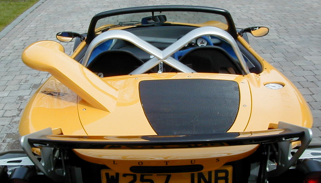
Finally after several more weeks had passed Simon delivered the finished article which he had christened “The Boost Tube” for fitting to the car.
Click on thumbnails for enlarged pictures of the real thing
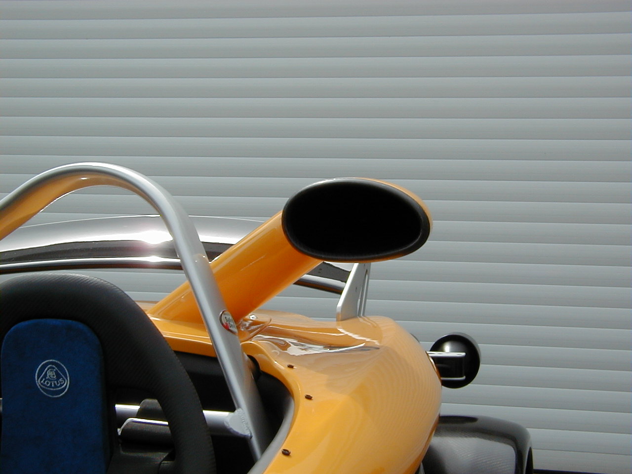
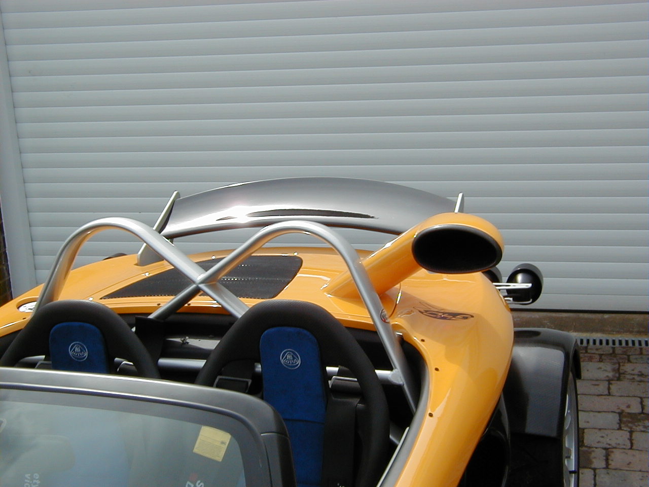
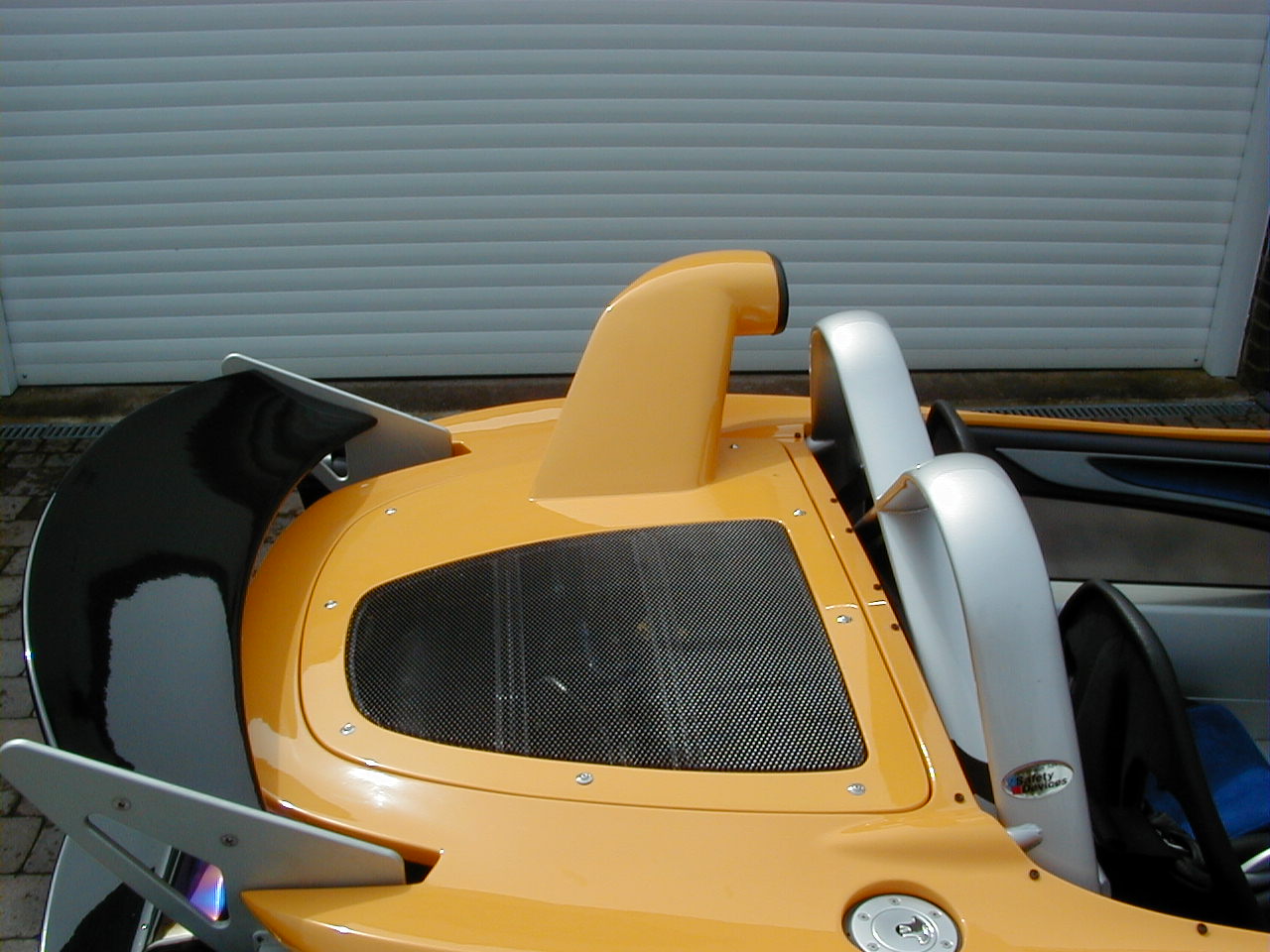

I just could not believe how light the thing was , although bigger than the existing lid it weighed a lot less (Boost Tube 1.8kg, Standard 2.3kg).
Even though it was late evening and very cold I
just couldn’t resist taking the car out to see what it was like. My
initial impressions were :
- Crisper
throttle response.
- Magnificent induction roar under load (similar to a superbike)
- More free revving engine.
However these impressions are all subjective and the
psychological effect of different engine note and increased noise would
tend to influence your judgment, the proof of the design would only come
with detailed testing.
Testing Time
On 4th April 2001 testing was undertaken at a suitable location in the Colchester area.
Pressure Testing was carried out using a GM Map
Sensor connected to a Pico technologies
interface card and laptop computer. A pressure
sensor tapping from the Map sensor was positioned in the filter cone
attached to the airbox inlet
Temperature testing was carried out using two Pico external temperature sensors connected to the Pico technologies interface card and laptop computer. The ambient temperature sensor was taped to the top of the passenger side door mirror and the engine inlet temperature sensor was positioned in the filter cone attached to the airbox inlet.
Temperature Effect
The day was cool and overcast and the first test run was carried out with the standard engine compartment lid and the air inlet flexi duct in its normal 190 Modified position (i.e. pointing towards the air inlet pod just behind the roll bar strut).
Ambient temperature initially was 9 Deg C and as we started the engine and drove away the engine inlet temperature started to rise and after several minutes it had risen to 19 Deg C. Engine air inlet temperature during the rest of the test fluctuated between 9 and 11 Deg C above ambient temperature
The same test was repeated with the Boost Tube
fitted and connected to engine air inlet flexiduct. The results were
significant: after a couple of minutes running the air inlet temperature
remained within 0.1 of a
degree of the ambient figure- within the accuracy of our measuring
equipment this was to all intents the same as the ambient air temperature.
Some lower than ambient temperatures were
recorded, possibly due to the ambient sensor being exposed to sunlight and
the boost tube sensor being in darkness.
Click here to view temperature comparison charts from our test
Pressure Effect
Examination of the pressure figures revealed that with the standard engine compartment lid, the pressures at the filter were around ambient pressure with a slight negative pressure apparent during heavy acceleration, at no time (even at 120mph) was a significant positive pressure measured.
Examining the pressure figures with Boost Tube fitted showed a small positive pressure which varied directly in proportion to speed. The most accurate correlation was found by allowing the vehicle to coast down from 120 mph with the engine off.
The additional pressure produced by the Boost Tube
varied from 11.59 mbar at 120mph to 4.48
mbar at 40mph.
Click here to view selected pressure charts from our test.
The theoretical effect on vehicle power
The beneficial effects on vehicle horsepower can be calculated and sumarised as follows :
2.77PS
ram effect @120mph based on 11.59mbar (0.1622psi) boost.
3.75PS
Temperature effect at all speeds, based on 10’C intake temperature drop.
Total
effect at 120mph 6.52PS.
Click
here to view the theoretical calculations in full.
Boost Tube Availability
The Boost Tube is manufactured by ReVerie
Limited, who specialise in air intake systems and supply Caterham cars the
carbon intake system for the R500.
Construction is
4ply CFO 300 LTM 262 x 2 twill carbon prepreg, with some HFO0100 LTM26
Carbon/Kevlar 2x2 twill prepreg reinforcement between layers 2&3 &
localised reinforcement between tube & panel surface joint. The whole
assembly is cured using aerospace techniques in an autoclave pressurised
at 30psi.
The completed boost tube is available painted in body colour, matt carbon, or any other finishes required.
The approximate cost (finished in standard
body colour or matt carbon) is £1650
excluding VAT, and excluding delivery.
ReVerie Contact details are :
ReVerie
Limited
5 Church Lane
Lexden
Colchester
Essex
CO3 4AB
Tel: (+44)
1206 367439
Fax: (+44) 1206 367423
Mobile: 07879 495214
Email : sales@reverie.ltd.uk
or click the logo below to connect to their website.

Owners Verdict
The Boost Tube represents an easily fitted way of
increasing the power of your 340R by between 4 and 7 PS dependant upon
speed.
It can be easily reverted to standard if required for
reduced noise requirements and a more conservative appearance.
Owners of upgraded 190 cars will find it difficult to
implement alternative significant increases in power without the
expenditure of large sums of money and vehicle downtime – this fits in
five minutes.
Benefits :
- More power
- Reduced weight
- Better throttle response
- Better
engine cooling
- More noise
Drawbacks :
- More noise
- Cost – but at this level, nothing comes cheap.
To support this site, please click on our sponsors link below :
Air Conditioning Manchester - by Celsius Air Conditioning Ltd